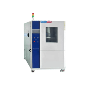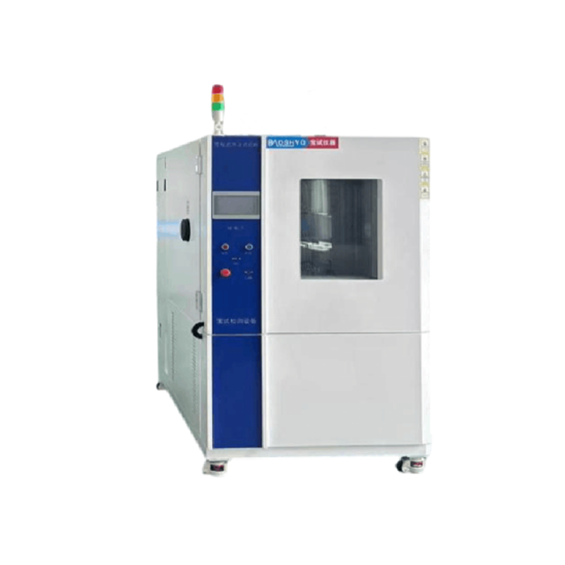
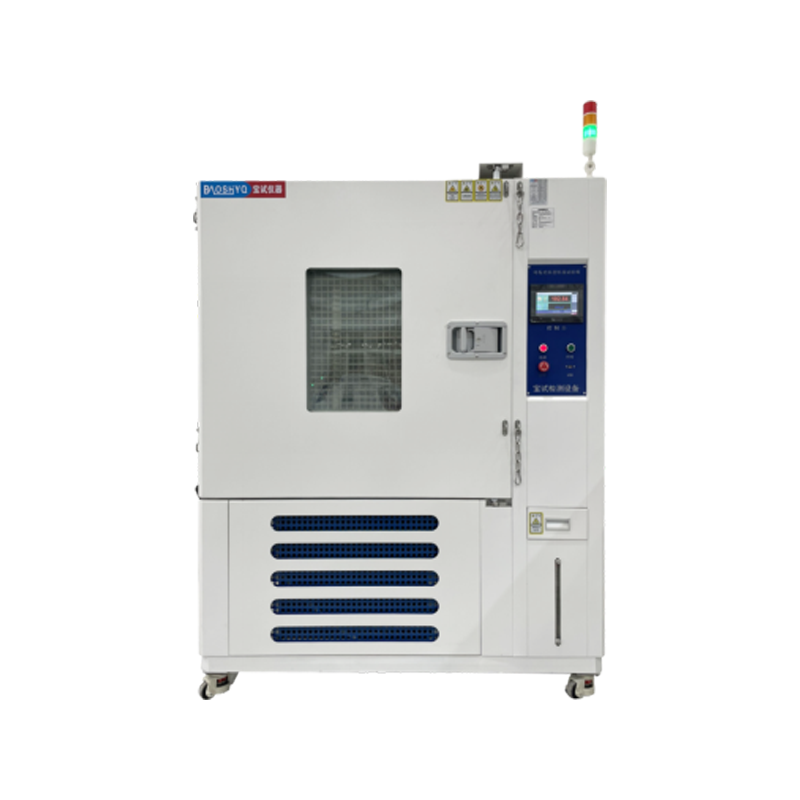
- Technical Parameters
| Item No. | Parameter Name | Technical parameters |
| 1.1 | Equipment Name | Programmable Rapid Temperature Change Test Chamber |
| 1.2 | Equipment Introduction | The Programmable Rapid Temperature Change Test Chamber is a type of large-scale climate simulation environmental equipment. It is suitable for conducting temperature and humidity aging tests on electrical and electronic products, covering industries and fields including new energy, automotive, household appliances, semiconductors, electronics, aerospace, colleges and universities, as well as instrument and meter components. Additionally, it is used to perform adaptability tests under environmental conditions such as high temperature, low temperature, damp heat, and alternating damp heat. |
| 1.3 | Equipment Model | BS-1000CD-5F |
| 1.4 | Effective Volume | 1000L |
| 1.5 | Internal Chamber Dimensions | 1000*1000*1000 (W*H*D)(mm) |
| 1.6 | External Dimensions | Front-back Structure:1250*2120*2250(W*H*D) (mm)
Lateral Structure:1650*2100*1750(W*H*D) (mm) ( Subject to the final confirmed 3D drawing ) |
| 1.7 | Temperature Range | -40℃~150℃ |
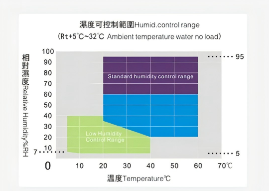
| 1.8 | humidity range | 20~98%R. H
(Temp. & Humidity Comparison Table) |
| 1.9 | Heating Rate | -40℃ ~ 150℃ ≥5℃/min
(Full-process Non-linearity & No-load Acceptance) |
| 1.10 | Cooling Rate | 150℃ ~ -40℃ ≥5℃/min
(Full-process Non-linearity & No-load Acceptance) |
| 1.11 | Temperature and Humidity Display Accuracy | Temperature:0.01℃
Humidity:0.1%R.H |
| 1.12 | Temperature and Humidity Deviation | Temperature:±2℃
Humidity: When ≥75%RH, the humidity error shall be ≤+2 to -3%RH Humidity: When <75%RH, the humidity error shall be ≤±5%RH |
| 1.13 | Temperature and Humidity Fluctuation | Temperature:≤±0.5℃
Humidity:+2/-3%R.H |
| 1.14 | Temperature and Humidity Uniformity | Temperature:≤2℃
Humidity:+2/-3%R.H |
| 1.15 | Cooling Method | Air Cooling
(Water cooling is recommended as an optional configuration) |
| 1.16 | Weight | 700KG |
| 1.17 | Power | 380V/28.5KW |
| 1.18 | Others | All the above performance indicators refer to the data measured under the conditions of no load, no test sample, and ambient temperature of 25±2℃.
Operating Noise:70dB (measured at 1 meter from the chamber door and 1.5 meters in height). |
- Compliant Test Standards
| Item No. | Standards | Explanation of Standards |
| 2.1 | General standards | GB/T2423.2-2008
Test Method: High Temperature |
| GB/T 2423.1-2008
Test method: Low Temperature |
||
| GJB150.4A-2009
Low Temperature Test Method |
||
| GJB150.3A-2009
High Temperature Test Method |
||
| G/BT 2423.4-2008/IEC6008-2-30:2005
Test Db: Alternating Damp Heat Method |
||
| GBT 2424.6-2006
Environmental Testing for Electrical and Electronic Products – Performance Qualification Report of Temperature and Humidity Test Chambers |
||
| GB/T10586-2006
Technical Specifications for Damp Heat Test Chambers |
||
| GBT 2424.5-2006
Environmental Testing for Electrical and Electronic products – Performance Qualification Report of Temperature Test Chambers |
||
| 2.2 | Acceptance Execution Standards | Manufacturing Standards:GB/T10586-2006,GB/T10592-2008 |
| Verification Standards :GB/T5170.2-2017,GB/T5170.5-2016 | ||
| Technical Standards: Acceptance shall be conducted in accordance with the signed technical index requirements |
- Equipment Structure
| Item No. | Description | Technical Specification Parameters |
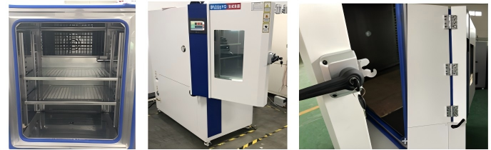
| 3.1 | Cabinet Structure | Integrated (left-right/front-back) frame structure, welded with national standard channel steel. The equipment is sturdy and durable, with low vibration and low noise during operation, while ensuring the overall reliability and safety performance of the equipment. |
| 3.2 | Inner Chamber Material | It adopts 1.0mm-thick SUS #304 stainless steel.
The entire inner chamber is fully welded to ensure its sealing performance, with a reinforced bottom design that supports an average load of ≥300KG. |
| 3.3 | Outer Shell Material | It adopts cold-rolled steel plates with a thickness of 1.2mm, featuring double-sided spraying treatment and a blue-white color(Customizable according to customer requirements, color samples or color codes are available upon request). |
| 3.4 | Thermal Insulation Material | The thermal insulation layer has a thickness of 100mm and uses fire-resistant, high-strength rigid polyurethane foam insulation material. Thermal insulation coefficient: less than 0.0212 kcal/(m・hour). |
| 3.5 | Cabinet Door Structure | It is a single door, a double-layer silicone rubber sealing strip is used between the door and the chamber to ensure sealing performance, featuring resistance to high and low temperatures and anti-aging properties. An anti-condensation and anti-frost electric heating device is installed on the door frame and door edge to prevent condensation from forming on the chamber surface. |
| 3.6 | Test Observation Window | One vacuum multi-layer explosion-proof glass viewing window is provided; the surrounding area of the window is equipped with coated heating for anti-frost protection to prevent water vapor condensation. A safe, high-brightness, energy-saving lighting lamp (with manual on/off control) is installed above the viewing window. |
| 3.7 | Air Duct Components | It adopts a circulating fan with a motor, an aluminum extended shaft, and a high/low temperature-resistant aluminum alloy multi-blade circulating fan, achieving forced convection vertical diffusion circulation. The air outlet is adjustable. |
| 3.8 | Sample Shelf | It is made of stainless steel, equipped with 2 sets of brackets, and can be freely adjusted up and down (customizable according to customer requirements). |
| 3.9 | Test Port | One test port with a diameter of 50mm is reserved on the left side of the chamber, and one set of silicone plug + sealing cover is provided. |
| 3.10 | Three-Color Indicator Light | Green for normal operation, yellow for standby, and red for fault alarm. |
| 3.11 | Drainage Trough | Drainage troughs are provided around the interior of the cabinet, facilitating the discharge of condensed water and preventing internal water accumulation. |
| 3.12 | Balance Hole | A pressure balance hole is installed inside the chamber to balance the pressure between the inside and outside of the chamber. |
| 3.13 | Swivel Caster | Swivel casters are installed at the bottom of the equipment, facilitating the relocation, movement and positioning of the equipment. |
 |
||
- Circulation System
| Item No. | Description | Technical Specification Parameters |
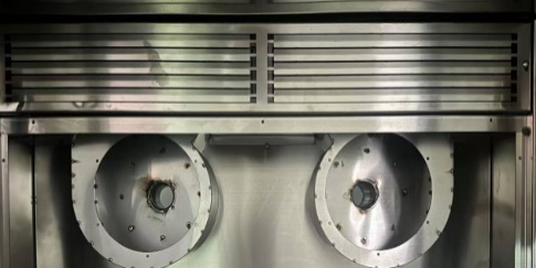
| 4.1 | Air Supply Method | It adopts a forced internal circulation mode with top air supply and bottom air return. The air deflector at the air outlet can disperse cold and hot air to the entire interior of the chamber, ensuring uniform and stable distribution. |
 |
||
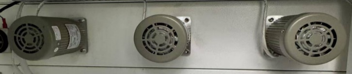
| 4.2 | Circulation Motor | It is a long-shaft motor, installed outside the chamber, avoiding the influence of temperature and humidity inside the chamber. The long shaft extends directly into the interior of the chamber, with silicone insulation and sealing. |
 |
||
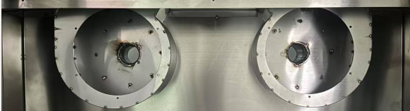
| 4.3 | Centrifugal Impeller | It is a multi-blade centrifugal circulating aluminum wind wheel, featuring light weight, large air volume, and high air pressure. Additionally, it exhibits resistance to high and low temperatures, a small expansion coefficient, and low operating noise. |
 |
||
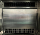
| 4.4 | Circulating Air Duct | The circulating air duct is matched with the refrigeration and heating system, and the sealing plate is closely attached to the evaporator and heating tube, allowing the circulating air to fully absorb the cold energy from the evaporator and the heat energy from the heating tube. |
 |
||
| 4.5 | Sensor | Class A Platinum Resistance PT100+T Temperature and Humidity Sensor, featuring stable operation and accurate detection. |
- Refrigeration System
| Item No. | Description | Technical Specification Parameters |
| 5.1 | Refrigeration Mode | Compressor-Based Refrigeration |
| 5.2 | Compressor | French “Tecumseh” Hermetic Compressor |
| 5.3 | Evaporator | High-Efficiency Multi-Stage Fin-and-Tube Evaporator with Hydrophilic Coating (Thickened Fin Type) |
| 5.4 | Condenser | Shell-and-Tube Condenser (Air-Cooled Type) |
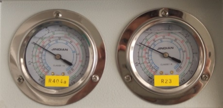
| 5.5 | Refrigerant | Fluoride-Free Eco-Friendly Refrigerant, DuPont (USA) R404A |
| 5.6 | Thermal Expansion Valve | The core control logic of the thermal expansion valve is: The opening degree of the expansion valve is controlled by the superheat degree of the gaseous refrigerant at the evaporator outlet, thereby adjusting the flow rate of refrigerant entering the evaporator. |
| 5.7 | Oil Separator | The core function of the oil separator is to separate the refrigerating oil and refrigerant, allowing each substance to perform its respective function as required and preventing oil films from reducing heat exchange efficiency. |
| 5.8 | Filter-Drier | The filter-drier consists of two parts: the filter and the dryer. The filter is used to block solid particles such as iron filings, welding slag, and dirt, preventing them from clogging the passages; the dryer is used to absorb moisture circulating with the refrigerant, avoiding “ice blockage” inside the pipelines. |
| 5.9 | Solenoid Valve | Danfoss Solenoid Valve (for coarse adjustment of the cooling capacity of the entire refrigeration system) |
| 5.10 | Leak Detection Method | Nitrogen purging and pressure holding for 24 hours is adopted for leak detection testing of all pipelines in the entire system. |
 |
||
| 5.11 | Vibration Damping Design | Compressor Base and Vibration Isolation Treatment: The base features a water-leakage prevention design. It is a self-evaporating waterproof base that effectively prevents condensed water from leaking out. Vibration isolation treatment is applied to moving components such as the compressor and fan, achieving a low-noise design. |
- Heating System
| Item No. | Description | Technical Specification Parameters | |
| 6.1 | Heating Method | It adopts an imported SSR (Solid-State Relay) for driving, featuring contactless control, no noise, no electric arc, and stable reliability. | |
| 6.2 | Heating Tube | It adopts a stainless steel finned nickel-chromium wire high-speed heater. | |
| 6.3 | Heating System and Electrical Components | It is a completely independent system that does not affect the refrigeration and humidification systems. Temperature control is achieved through microcomputer calculation and PID automatic adjustment; the output power changes based on the comparison result between the actual temperature value and the set temperature value, so as to achieve high precision, high efficiency, and high stability. Major low-voltage electrical components all adopt products from well-known brands: “Schneider” AC contactors and thermal overload relays, “OMRON” small intermediate relays, and Delixi signal lamps, switches, and circuit breakers. | 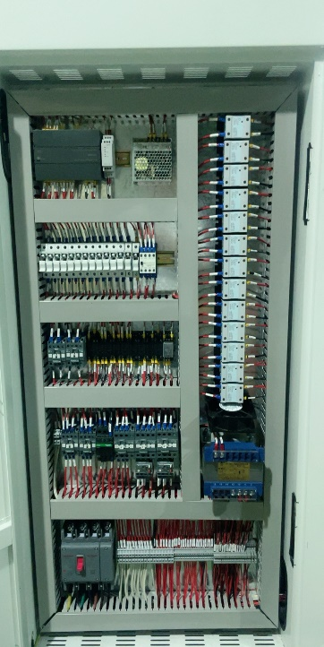 |
- Humidification System
| Item No. | Description | Technical Specification Parameters |
| 7.1 | Humidification Method | It is a fully automatic humidification module system with integrated closed-loop humidity control, designed and manufactured using advanced technology. It is an improved and upgraded multi-functional integrated humidification system,featuring superior characteristics such as fast humidification, high efficiency, ultra-low failure rate, and higher reliability. It adopts SSR-driven contactless control and intelligent PID automatic calculation to adjust output power. |
| 7.2 | Water Level Control | It features automatic water level control and automatic water filling functions, which make the humidification system more efficient, the control more stable, and the equipment operation more reliable. These functions avoid the drawback of high failure rates in humidification systems and overall improve the equipment’s reliability. |
| 7.3 | Humidification Unit | It features a closed integrated structure, which is easy to install and can be mounted outside the chamber/room. The system structure is simpler, more efficient, and more practical. |
| 7.4 | humidity sensor | Electronic Temperature and Humidity Sensor: Imported electronic temperature and humidity sensors are selected. |