
- Technical Parameters
| Item No. | Parameter Name | Technical parameters |
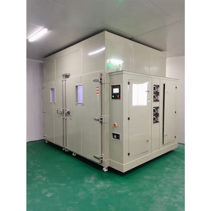
| 1.1 | Equipment Name | Walk-in Composite Salt Spray Test Chamber |
| 1.2 | Equipment Introduction | Cyclic corrosion testing is a more realistic salt spray test than traditional steady-state exposure. Because actual outdoor exposure usually involves both dry and wet environments, simulating these natural and periodic conditions makes laboratory accelerated testing meaningful. Studies have shown that after cyclic corrosion testing, the relative corrosion rate, structure, morphology of samples are very similar to the outdoor corrosion results. Therefore, cyclic corrosion testing is closer to real outdoor exposure than traditional salt spray spraying methods. They can effectively evaluate many corrosion mechanisms, such as general corrosion, electrochemical corrosion and crevice corrosion.
This equipment is designed to simulate and enhance the impact of the environment on metal materials exposed to salt-contaminated outdoor atmospheres that can accelerate corrosion. The equipment includes a test method for cyclically exposing test pieces to salt spray, dry and humid heat environments. The test of this equipment is a comparative test, and the test results cannot predict the long-term corrosion resistance of the same metal materials used under such environmental conditions. However, this method can still provide valuable information on the relevant performance of materials exposed to salt-contaminated environments similar to the test conditions. Compared with traditional accelerated corrosion tests, such as neutral salt spray test, acetic acid salt spray test, and copper-accelerated acetic acid salt spray test (CASS), the greatest advantage of this equipment’s test is that it can better reproduce the corrosion occurring in outdoor salt-contaminated environments. |
| 1.3 | Equipment Model | BS-B-3500D |
| 1.4 | Effective Volume | 3500L |
| 1.5 | Internal Chamber Dimensions | 1500×1500×1500(W*H*D)(mm) |
| 1.6 | External Dimensions | 1700×3500×2300(W*H*D)(mm) |
| 1.7 | Brine Tank Volume | 100L |
| 1.8 | Pure Water Tank Volume | 100L (The water tank supports automatic water replenishment) |
| 1.9 | Door Opening Method | Manual door opening |
| 1.10 | Test Chamber Temperature Range | +20℃~+60℃ |
| 1.11 | Relative Humidity | 20%-98%RH |
| 1.12 | Saturation Tank Temperature | +35℃~+70℃ |
| 1.13 | Temperature Uniformity | ≤2℃ |
| 1.14 | Temperature Fluctuation | ≤±0.5℃ |
| 1.15 | Settling Amount | 1-2ml/80cm²/h Continuously Adjustable |
| 1.16 | Test Methods | Programmable salt spray, humid heat, drying, standard climate |
| 1.17 | Defogging Method | Automatic defogging, fog discharge through air extrusion |
| 1.18 | Common Test Conditions | Neutral Salt Spray Test:
Test chamber temperature: 35℃; Saturation tank temperature: 47℃ 5% mass ratio NaCl solution spray; Settling amount: 1~2ML/H*80cm² Humid Heat Storage Test: Test chamber temperature: 25℃, Humidity: 95%r.h. Test chamber temperature: 40℃, Humidity: 93%r.h. Test chamber temperature: 50℃, Humidity: 70%r.h. Test chamber temperature: 50℃, Humidity: ≥95%r.h. Standard Atmosphere Storage Test: Test chamber temperature: 23℃, Humidity: 50%r.h. Test chamber temperature: 25℃, Humidity: 45%r.h. Hot Drying Test: Test chamber temperature: 60℃, Humidity: <30%r.h. Conversion from salt spray condition to dry condition: ≤60min Conversion from dry condition to humid heat condition: ≤30min Conversion from humid heat condition to salt spray condition: ≤30min |
| 1.19 | Equipment Weight | 850kg |
| 1.20 | Power | 380V 13KW |
| 1.21 | Others | 1. The above performance indicators refer to the data measured under the conditions of no load, no test samples, and ambient temperature of 25±2℃.
2. 70dB (1 meter away from the box door, 1.5 meters high) |
- Compliant Test Standards
| Item No. | Standards | Explanation of Standards |
| 2.1 | General standards | GB/T2423.17 Environmental Testing – Test Ka – Salt Spray |
| GB/T2423.18 Environmental Testing – Test Kb – Salt Spray, Alternating (Sodium Chloride Solution) | ||
| IEC 60068-2-11 Environmental Testing – Part 2-11: Tests – Test Ka: Salt Spray Test Method | ||
| IEC 60068-2-52 Environmental Testing – Part 2-52: Tests – Test Kb: Salt Spray, Alternating (Sodium Chloride Solution) | ||
| GB10587 Technical Conditions for Salt Spray Test Chambers | ||
| ASTM B117-16 Salt Spray Testing | ||
| GJB150.11A “Laboratory Environmental Test Methods for Military Equipment – Part 11: Salt Spray Test” | ||
| Q SOR T1-172-2020 | ||
| 2.2 | Acceptance Execution Standards | Manufacturing Standards: GB/T10586-2006, GB/T10592-2008 |
| Verification Standards: GB/T5170.2-2017, GB/T5170.5-2016 | ||
| Technical Standards: Acceptance according to the signed technical index requirements |
- Equipment Structure
| Item No. | Description | Technical Specification Parameters |
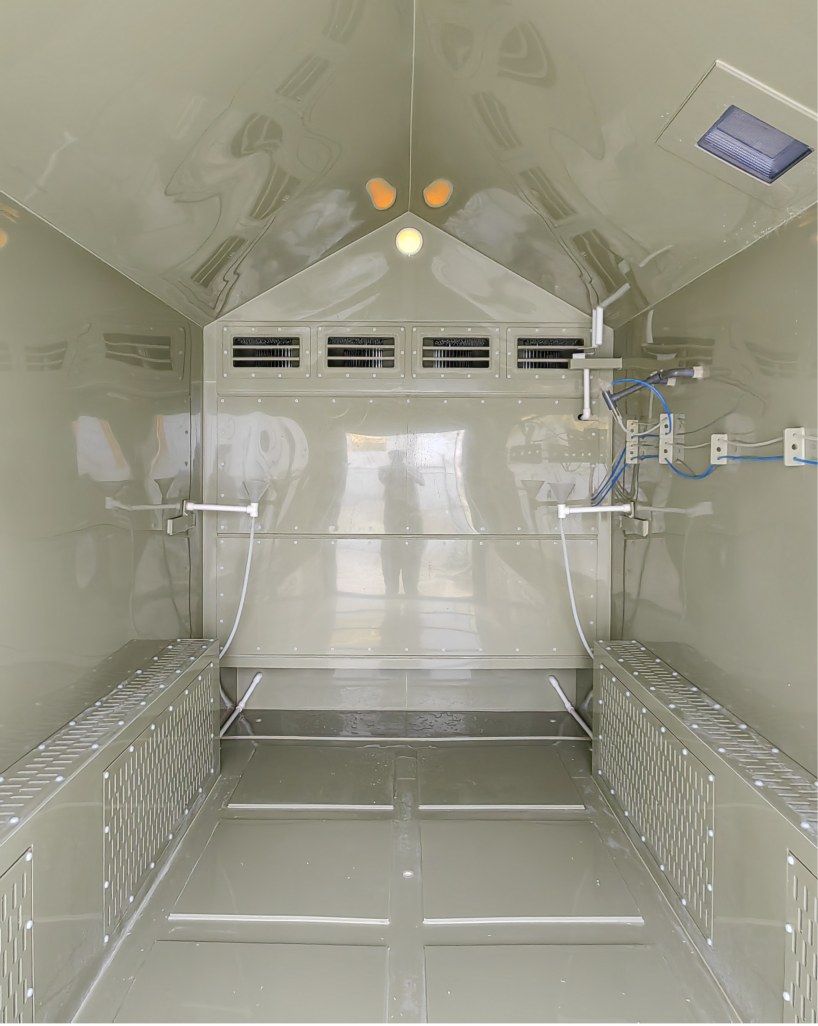
| 3.1 | Inner and Outer Chamber Material | Both the inner and outer chambers of this machine are made of Grade A beige PP (thickness 8~12mm) resistant to high temperature, high humidity and high corrosion. They are welded using advanced annular three-dimensional reinforcement technology, with a solid structure and elegant appearance. It is suitable for various test specifications such as salt water spray and copper acetate tests. |
| 3.2 | Reagent Supplement Port | Large-capacity hidden integrated reagent supplement tank, easy to clean and operate. |
| 3.3 | Chamber Door | Adopts a single-door structure, door opening size: 1200×1400 (W×H) (mm). A large-sized hollow observation window (400*500mm) is installed on the door of the test chamber. A special double-layer silicone rubber seal is used between the door and the chamber. |
| 3.4 | Heating Method | During the salt spray test phase, the bottom water tank steam heating method is adopted, which has a fast heating rate and reduces standby time. When the temperature is reached, it automatically switches to constant temperature state, with precise temperature and low power consumption. The titanium alloy heating tube is resistant to acid and alkali corrosion and has a long service life. |
| 3.5 | Indoor Top Plate | The top plate structure inside the test chamber is a 120-degree bevel angle, which can prevent condensed water droplets from falling on the test samples. The condensed water in the chamber can be continuously discharged through the diversion grooves around. |
| 3.6 | Bottom Plate Bearing Capacity | The bottom of the test chamber adopts an integral channel steel structure frame to ensure the overall bearing capacity and stability of the test chamber. The bottom of the channel steel structure is equipped with Fuma movable casters for easy overall movement of the equipment.
|
| 3.7 | Saturated Air Tank | Located at the bottom of the control box, made of SUS#304 stainless steel plate, it plays the role of filtration, heating and humidification, so that the purified air reaches the saturation temperature and humidity before being sprayed by the nozzle. The saturator has an automatic water replenishment function. |
| 3.8 | Measuring Cylinder | Collects the spray volume of each test, with a maximum scale of 50ml each time. |
| 3.9 | Pressure Regulating Valve | Manually adjust the intake pressure and spray pressure. The intake pressure is controlled at 0.3mPa; the spray pressure is controlled at 0.07-0.17mPa. (The above pressures have been adjusted before leaving the factory; users generally do not need to adjust them again) |
| 3.10 | Pressure Gauge | The pressure displayed by the pressure gauge pointer is the pressure when the air from the saturated air tank is delivered to the nozzle for spraying. |
| 3.11 | Water Replenishment System | 1. Water replenishment for the test chamber and pressure tank: Two water replenishment control systems (manual and automatic) are available, which can be connected to the tap water pipe for automatic water replenishment or manual water addition, easy to use.
Note: If the tap water has too many impurities or is acidic/alkaline, a filter should be installed at the water inlet. 2. Chemical solution replenishment: Adopts a large hidden internal water tank with manual water replenishment method. |
| 3.12 | Fog Discharge Pipe | 50mm diameter PVC hard plastic pipe. When the salt spray test chamber is working, it releases the pressure caused by spraying, and the excess water in the chamber also overflows from here. |
| 3.13 | Electrical Control Cabinet | The circuit control board and other components are fixed in positions convenient for inspection and maintenance. It adopts a door lock opening type side cover door, which is not only beautiful but also convenient for maintenance. |
| 3.14 | Control Panel | Touch screen control: Water shortage indicator, over-temperature indicator, end indicator, spray indicator, defogging indicator, test chamber temperature controller, pressure tank temperature controller, pressure gauge, main power switch, operation switch, timing switch, spray switch, defogging switch. |
- Air Circulation System
| Item No. | Description | Technical Specification Parameters |
| 4.1 | Salt Spray Test Phase (No Air Circulation) | 1. Air conditioning method: The temperature of the test chamber is balanced and adjusted through the air flow of the spray during the test and the thermal radiation set at the bottom of the chamber to ensure uniform temperature field in the test chamber.
2. Heating method: Air dry heating radiation. |
| 4.2 | Humid Heat Test Phase (With Air Circulation) | 1. Air conditioning method: Forced air circulation balanced temperature and humidity control, using corrosion-resistant multi-blade centrifugal fan and low-noise motor.
2. Air circulation device: Air supply circulation system composed of adjustable circulation air duct structure, which effectively ensures the uniformity of temperature in the chamber. 3. Heating method: Corrosion-resistant titanium alloy air heater. |
- Heating System
| Item No. | Description | Technical Specification Parameters |
| 5.1 | Heating Method | Steam heating method is adopted, which has a fast heating rate and reduces standby time. When the temperature is reached, it automatically switches to constant temperature state, with precise temperature and low power consumption. The titanium alloy heating tube is resistant to acid and alkali corrosion and has a long service life. |
| 5.2 | Heating Tube | Uses stainless steel finned nickel-chromium wire high-speed heater. |
| 5.3 | Heating System | Temperature control is calculated by microcomputer and automatically adjusted by PID. The output power changes with the comparison result between the actual temperature and the set temperature to achieve high precision, high efficiency and high stability. |
- Humidification System
| Item No. | Description | Technical Specification Parameters |
| 6.1 | Humidification Method | External humidification system, no need to drain water during low temperature, easy to achieve low humidity control. |
| 6.2 | Humidification Heating Tube | Stainless steel heating tube with over-temperature protection. |
| 6.3 | Control Valve | Adopts original automatic humidification pipeline control valve, which automatically opens and closes the channel to prevent corrosion of the humidification system by salt spray during the salt spray test phase. |
- Refrigeration System
| Item No. | Description | Technical Specification Parameters |
| 7.1 | Refrigeration Compressor | Imported refrigeration compressor from “Tecumseh” France |
| 7.2 | Cooling Method | Air-cooled type |
| 7.3 | Refrigerant | Environmentally friendly refrigerant |
| 7.4 | Main Refrigeration Accessories | Solenoid valve(Castel) from Italy; Filter drier(083) from USA, etc. |