- Technical Parameters
| Item No. | Parameter Name | Technical parameters |
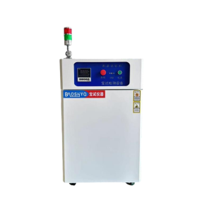
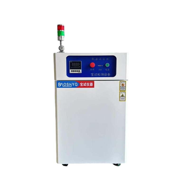
| 1.1 | Equipment Name | Touchscreen-type High-Temperature Test Chamber |
| 1.2 | Equipment Introduction | This series of products is suitable for new energy, aerospace products, information electronic instruments and meters, materials, electrical engineering (products/components), automotive (products), metals, electronic products, various electronic components, and other fields. It is used to inspect their various performance indicators under high-temperature environments and for quality management purposes. |
| 1.3 | Equipment Model | BS-1000GC |
| 1.4 | Effective Volume | 1000L |
| 1.5 | Internal Chamber Dimensions | 1000*1000*1000 (W*H*D)(mm) |
| 1.6 | External Dimensions | 1250*1480*1350(W*H*D) (mm) |
| 1.7 | Temperature Range | RT+10℃→260℃ |
| 1.8 | Heating Rate | RT+10℃→260℃ ≥3℃/min
(Full-process Non-linearity & No-load Acceptance) |
| 1.9 | Temperature Display Accuracy | Temperature:0.1℃ |
| 1.10 | Temperature Deviation | Temperature:±2℃ |
| 1.11 | Temperature Fluctuation | Temperature:≤±0.5℃ |
| 1.12 | Temperature Uniformity | Temperature:≤2.5℃ |
| 1.13 | Weight | 350KG |
| 1.14 | Power | 380V/11KW |
| 1.15 | Others | All the above performance indicators refer to the data measured under the conditions of no load, no test sample, and ambient temperature of 25±2℃.
Operating Noise:70dB (measured at 1 meter from the chamber door and 1.5 meters in height). |
- Compliant Test Standards
| Item No. | Standards | Explanation of Standards |
| 2.1 | General standards | GB-T2423.3-2006(IEC6008-2-78-2001)
Test Cab: Constant Test Method |
| GB-150.3A-2009
High-Temperature Test Method |
||
| GBT 2423.2-2008
Environmental Testing for Electrical and Electronic Products – Part 2: Tests – Test B: High Temperature |
||
| 2.2 | Acceptance Execution Standards | Manufacturing Standards:GB/T10586-2006,GB/T10592-2008 |
| Verification Standards :GB/T5170.2-2017,GB/T5170.5-2016 | ||
| Technical Standards: Acceptance shall be conducted in accordance with the signed technical index requirements |
- Equipment Structure
| Item No. | Description | Technical Specification Parameters |
| 3.1 | Cabinet Structure | It features an integrated frame structure, welded with national standard channel steel, ensuring the equipment is robust and durable, with low vibration and low noise during operation. Meanwhile, it guarantees the overall reliability and safety performance of the equipment. |
| 3.2 | Inner Chamber Material | It adopts 1.0mm-thick SUS #304 stainless steel.
The entire inner chamber is fully welded to ensure its sealing performance, with a reinforced bottom design that supports an average load of ≥300KG. |
| 3.3 | Outer Shell Material | It adopts cold-rolled steel plates with a thickness of 1.2mm, featuring double-sided spraying treatment and a blue-white color(Customizable according to customer requirements, color samples or color codes are available upon request). |
| 3.4 | Thermal Insulation Material | The thickness of the insulation layer is 100 mm, and the insulation medium is glass fiber cotton. |
| 3.5 | Cabinet Door Structure | It adopts a single-door design. A double-layer silicone rubber sealing strip is used between the door and the cabinet, which is resistant to high and low temperatures and aging, ensuring sealing performance. This design allows test personnel to open the door freely at the lock and hinge positions. |
| 3.6 | Air Duct Components | It adopts a circulating fan with a motor, an aluminum extended shaft, and a high/low temperature-resistant aluminum alloy multi-blade circulating fan, achieving forced convection vertical diffusion circulation. The air outlet is adjustable. |
| 3.7 | Sample Shelf | It is made of stainless steel, equipped with 2 sets of brackets, and can be freely adjusted up and down (customizable according to customer requirements). |
| 3.8 | Test Port | One test port with a diameter of 50mm is reserved on the left side of the chamber, and one set of silicone plug + sealing cover is provided. |
| 3.9 | Three-Color Indicator Light | Green for normal operation, yellow for standby, and red for fault alarm. |
| 3.10 | Balance Hole | A pressure balance hole is installed inside the chamber to balance the pressure between the inside and outside of the chamber. |
| 3.11 | Swivel Caster | Swivel casters are installed at the bottom of the equipment, facilitating the relocation, movement and positioning of the equipment. |
- Circulation System
| Item No. | Description | Technical Specification Parameters |
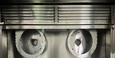
| 4.1 | Air Supply Method | It adopts a forced internal circulation mode with top air supply and bottom air return. The air deflector at the air outlet can disperse cold and hot air to the entire interior of the chamber, ensuring uniform and stable distribution. |
 |
||
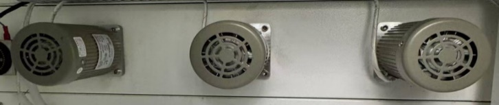
| 4.2 | Circulation Motor | It is a long-shaft motor, installed outside the chamber, avoiding the influence of temperature and humidity inside the chamber. The long shaft extends directly into the interior of the chamber, with silicone insulation and sealing. |
 |
||
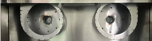
| 4.3 | Centrifugal Impeller | It is a multi-blade centrifugal circulating aluminum wind wheel, featuring light weight, large air volume, and high air pressure. Additionally, it exhibits resistance to high and low temperatures, a small expansion coefficient, and low operating noise. |
 |
||
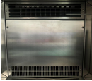
| 4.4 | Circulating Air Duct | The circulating air duct is matched with the refrigeration and heating system, and the sealing plate is closely attached to the evaporator and heating tube, allowing the circulating air to fully absorb the cold energy from the evaporator and the heat energy from the heating tube. |
 |
||
| 4.5 | Sensor | Class A Platinum Resistance PT100+T Temperature and Humidity Sensor, featuring stable operation and accurate detection. |
- Heating System
| Item No. | Description | Technical Specification Parameters | |
| 5.1 | Heating Method | It adopts an imported SSR (Solid-State Relay) for driving, featuring contactless control, no noise, no electric arc, and stable reliability. | |
| 5.2 | Heating Tube | It adopts a stainless steel finned nickel-chromium wire high-speed heater. | |
| 5.3 | Heating System and Electrical Components | It is a completely independent system that does not affect the refrigeration and humidification systems. Temperature control is achieved through microcomputer calculation and PID automatic adjustment; the output power changes based on the comparison result between the actual temperature value and the set temperature value, so as to achieve high precision, high efficiency, and high stability. Major low-voltage electrical components all adopt products from well-known brands: “Schneider” AC contactors and thermal overload relays, “OMRON” small intermediate relays, and Delixi signal lamps, switches, and circuit breakers. | 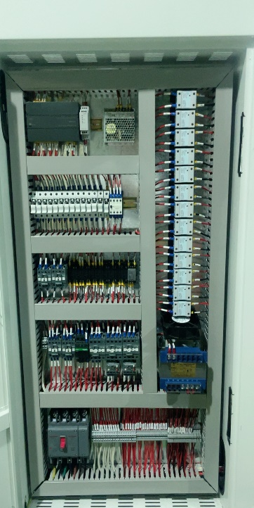 |
- Control System
| Item No. | Description | Technical Specification Parameters |
| 6.1 | Control Method | Touchscreen Control + Anti-Integral Windup PID, BTC Balanced Temperature Control Method |
| 6.2 | Screen Display | 7-Inch LCD Color Touch Interactive Display Screen
It can display the following information: · Temperature set value and current temperature value · Temperature output value · Executing program group, executing program segment, program time, and time signal control status · Auto-tuning screen and program standby/segment skip screen · Data records and curve status screen · Current curve, editable program curve, and historical operation curve · Fault prompts and simple troubleshooting guidance |
| 6.3 | Temperature setting | Adjust according to the device’s temperature operating range (upper limit +5℃, lower limit -5℃) |
| 6.4 | Communication | USB and LAN Communication Interfaces, which can be used as monitoring and remote control systems and for recording test data |
| 6.5 | Program Storage Capacity and Control Functions | Usable Program Quantity: Maximum 120 groups; each program can consist of 1~99 segments
Usable Memory Capacity: 1200 segments · Repeatable execution commands: Each command can be executed up to 999 times · Program ramp rate can be set via the time axis · Programs can be set to link with each other · Program creation adopts simple interactive operation with functions such as editing, deleting, and inserting · 4 groups of time signal output control (capable of controlling DUT ON/OFF actions) · Equipped with 9 groups of PID parameter settings · During program execution, it has segment skipping and holding functions · Capable of curve display and data acquisition; date and time adjustment functions; key and screen lock (LOCK) function · Can be connected to a computer for use · 8-point DI (Digital Input) for abnormal input and 10-point DO (Digital Output) signal control
|
| 6.6 | Running Mode | Program Mode / Fixed-Value Mode |
| 6.7 | Display Accuracy | Temperature:0.1℃ Time:1min |
| 6.8 | Login Method | Chinese/English Name Login / Chinese/English Test Login / Operation Time Display |
| 6.9 | Deviation Calibration | It prevents parameter deviations caused by various factors; after calibration, the temperature and humidity values can be more accurate and meet standards. |
| 6.10 | Power Failure Memory Function | Power Failure Recovery Modes: Hot Start / Cold Start / Stop; Maximum Power Failure Memory Duration: 3 Years |
| 6.11 | Scheduled Power-On Function | Supports flexible setting of the power-on time; after the main power is turned on, the machine will automatically operate when the set time is reached. |
| 6.12 | Others | Fault Alarm with Cause & Troubleshooting Prompt Function, Power Failure Protection Function, Upper/Lower Temperature Limit Protection Function, Timing Function (Auto-Start & Auto-Stop Operation), Self-Diagnosis Function |
- Safety Protection Device
| Item No. | Technical Specification Parameters |
| 7.1 | Adjustable Over-Temperature Protection |
| 7.2 | Air Conditioning Duct Extreme Over-Temperature |
| 7.3 | Overload and Short-Circuit Protection |