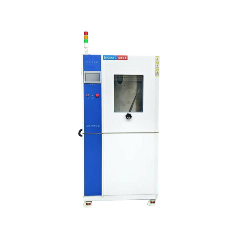
- Technical Parameters
| Item No. | Parameter Name | Technical parameters |
| 1.1 | Equipment Name | Dust and Sand Erosion Test Chamber |
| 1.2 | Equipment Introduction | 1. This test chamber is mainly used to determine the protection level of products against fine dust intrusion; the machine is strictly manufactured in accordance with the provisions of IP5/IP6 protection level testing in IEC 60529:2013, and is a test for inspecting sealing performance. Samples are exposed to a dusty air flow containing non-abrasive fine dust with a particle size less than 75μm. This method does not simulate natural or induced environments; a downward vertical air flow is specified in this test. For enclosures of specific grades, the internal pressure is lower than the external atmospheric pressure to promote dust intrusion; the amount of dust should ensure a high and uniform dust concentration. To this end, this test chamber is equipped with an air-blowing device for stirring test dust, which stirs the dust and blows it into the sealed test chamber. According to agreements and relevant regulations, the vacuum device for IP5 dustproof test samples is an optional accessory, while IP6 and La2 dustproof test samples should be connected to a vacuum pump to extract air from the inside of the samples, allowing the air flow in the dustproof test chamber to enter the samples through gaps, sleeves or other similar components. The pressure pipeline is equipped with a regulating valve, a monitoring vacuum pressure gauge, and a gas flow meter to measure the air extraction rate. The dust settled at the bottom of the test chamber is recycled. To prevent dust from adhering to the inner wall of the chamber and reducing the dust concentration inside the chamber, the bottom of the chamber is designed in a funnel shape and equipped with a dust shaking device for convenient dust recovery. The dust shaking cycle and time are controlled by the command output set by the central controller. The volume of the sample shall not exceed 25% of the internal volume of the test chamber, and the sample base shall not exceed 50% of the working horizontal area of the test chamber.
2. The test can be divided into: a. Testing only the sealed part of the sample; b. Testing representative components of the sample, including, for example, doors, air vents, supports, sealed shafts and other components. During the test, the precision components of the product such as terminals, collector rings, etc. shall remain in their original positions; c. Small samples with the same design details as the original sample. |
| 1.3 | Equipment Model | BS-1000SC |
| 1.4 | Effective Volume | 1000L |
| 1.5 | Internal Chamber Dimensions | 1000*1000*1000 (W*H*D)(mm) |
| 1.6 | External
Chamber Dimensions |
1250*1650*1450(W*H*D) (mm) |
| 1.7 | Temperature Range | RT+10~70℃ (Room Temperature +10~70℃) |
| 1.8 | Standard Wire Diameter of Metal Screen | 50μm |
| 1.9 | Standard Spacing Between Wires | 75μm |
| 1.10 | Talcum Powder Dosage | 2~4kg/m³ |
| 1.11 | Test Dust | The standard machine uses talcum powder; if the customer needs to use other dust, the dust shall be prepared by the customer themselves. |
| 1.12 | Dust Spraying and Settling Method | Free settling |
| 1.13 | Total Test Time | 0-999H (Adjustable) |
| 1.14 | Vibration Time | 0-999H (Adjustable) |
| 1.15 | Timing Accuracy | ±1 second |
| 1.16 | Vacuum Degree | 0-10Kpa (Adjustable) |
| 1.17 | Air Extraction Speed | 0-4800L/H (Adjustable) |
| 1.18 | Test Sample Power Supply | 220V |
| 1.19 | Weight | 260KG |
| 1.20 | Power | 220V 5KW |
| 1.21 | Others | All the above performance indicators refer to the data measured under the conditions of no load, no test sample, and ambient temperature of 25±2℃. |
- Compliant Test Standards
| Item No. | Standards | Explanation of Standards |
| 2.1 | General standards | GB2423.37-2006 Environmental Testing – Part 2: Tests – Test L: Dust Test |
| IEC 60068-2-68-1994 Environmental Testing – Part 2-68: Tests – Test L: Dust | ||
| GB4208-2008/IEC60529:2001 Degrees of Protection Provided by Enclosures (IP Code) | ||
| GJB150.12-2009 Laboratory Environmental Test Methods for Military Equipment – Part 12: Sand and Dust Test | ||
| GB7000.1-2007 Luminaires – Part 1: General Requirements and Tests (Chapter 9: Enclosure Protection Test) | ||
| GB10485 Dust Test Methods and equivalent JIS, DIN, MIL and other test standards | ||
| 2.2 | Acceptance Execution Standards | Manufacturing Standards:GB/T10586-2006,GB/T10592-2008 |
| Verification Standards :GB/T5170.2-2017,GB/T5170.5-2016 | ||
| Technical Standards: Acceptance shall be conducted in accordance with the signed technical index requirements |
- Equipment Structure
| Item No. | Description | Technical Specification Parameters |
| 3.1 | Cabinet Structure | Integrated frame structure, welded with national standard channel steel. The equipment is sturdy and durable, with low operating vibration and noise, while ensuring the overall reliability and safety performance of the equipment. |
| 3.2 | Inner Chamber Material | Adopts 1.0mm thick SUS #304 stainless steel; overall full welding treatment to ensure the sealing performance of the inner chamber. The bottom is reinforced with a design, with a bearing capacity of ≥300KG average load. |
| 3.3 | Outer Shell Material | Adopts cold-rolled steel plate with a thickness of 1.0MM, double-sided spray treatment, color: blue and white. (Customizable according to customer requirements, color samples or color codes provided by the customer). |
| 3.4 | Chamber Bottom | The bottom of the equipment is equipped with a replaceable dust device, which can conveniently replace 100% of the used dust. |
| 3.5 | Thermal Insulation Material | The thickness of the thermal insulation layer is 80MM, and the thermal insulation medium is glass fiber cotton. |
| 3.6 | Inside the Chamber | There is an air extraction pipe inside the chamber to complete the vacuum extraction of the sample (the sample needs to reserve an air extraction hole). To prevent dust from adhering to the chamber wall and condensing, a set of special devices is installed. The working time of the device is adjustable and can work automatically alternately. |
| 3.7 | Chamber Door Structure | Single-door design. A double-layer silicone rubber sealing strip is used between the door and the chamber, which is resistant to high and low temperatures and aging, ensuring sealing performance and facilitating the tester to open the door lock and door hinge freely. The door is equipped with a transparent observation window (tempered glass material), and an LED lighting lamp is installed inside the chamber to facilitate observation of the internal test situation. |
| 3.8 | Vacuum System | Equipped with a vacuum pump, vacuum pressure gauge, air filter, flow meter, pressure regulating triple unit, and connecting pipes. |
| 3.9 | Sample Shelf | Made of stainless steel rods, with 1 set of brackets. |
| 3.10 | Three-Color Light | A three-color light is installed: green indicates operation, yellow indicates stop, and red indicates fault. |
| 3.11 | Universal Wheels | Universal wheels are installed at the bottom of the equipment for convenient relocation, movement and positioning of the equipment. |
- Heating System
| Item No. | Description | Technical Specification Parameters | |
| 4.1 | Heating Method | A heater is installed in the circulating air duct to heat the dust to avoid dust condensation. The hoop-type mica sheet heating coil has safe and stable heat output; hoop-type mica sheet heating coil is adopted. | |
| 4.2 | Heating Tube | Uses stainless steel finned nickel-chromium wire high-speed heater. | |
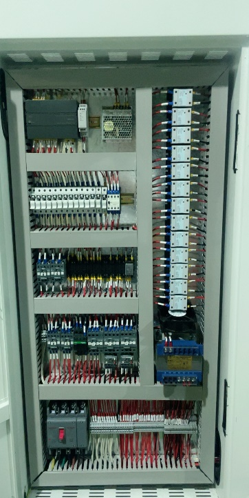
| 4.3 | Heating System and Electrical Components | Temperature control is calculated by microcomputer and automatically adjusted by PID. The output power changes with the comparison result between the actual temperature and the set temperature to achieve high precision, high efficiency and high stability.
Main low-voltage electrical components are all well-known brand products: “Schneider” AC contactors, thermal overload relays, “OMRON” small intermediate relays, Delixi signal lights, switches and circuit breakers, etc. |
 |
- Control System
| Item No. | Description | Technical Specification Parameters |
| 5.1 | Control Method | Color Touch Screen + PLC Control System |
| 5.2 | Screen Display | 7-inch LCD color touch screen
Displays temperature set value and current temperature value Displays temperature output value Displays automatic alternating of vibration and vibration stop time Controls the dust blowing fan, dust vibration and total test time Dust blowing time (stop/blow): continuous or periodic dust blowing, arbitrary time setting Displays power supply: off-on-off Displays fault prompts and simple troubleshooting methods |
| 5.3 | Temperature Setting | Adjust according to the temperature working range of the equipment (upper limit +5℃, lower limit -5℃) |
| 5.4 | Communication | USB and LAN communication interfaces, which can be used as monitoring and remote control systems and record test data |
| 5.5 | Operation Mode | Constant value mode |
| 5.6 | Preset Test Time | Maximum 99 hours and 59 minutes |
| 5.7 | Display Precision | Temperature: 0.01℃; Time: 1min |
| 5.8 | Login Method | English name login |
| 5.9 | Deviation Correction | Prevents parameter deviations caused by various factors; after correction, the temperature and humidity values can be more accurate and standard |
| 5.10 | Power Failure Memory Function | Can set the power failure recovery mode as: hot start / cold start / stop; maximum power failure memory time is 3 years |
| 5.11 | Scheduled Startup Function | Can set the startup time arbitrarily; the machine runs automatically when the power is turned on and the time is up |
| 5.12 | Auxiliary Functions | Fault alarm and cause, processing prompt function, power failure protection function, upper and lower limit temperature protection function, timing function (automatic start and automatic stop operation), self-diagnosis function |
- Safety Protection Device
| Item No. | Technical Specification Parameters |
| 6.1 | Adjustable over-temperature protection |
| 6.2 | Extreme over-temperature protection of air conditioning channel |
| 6.3 | Overload and short circuit protection |
- List of Main Accessories
| Item No. | Accessory Name | Quantity | Brand |
| 7.1 | Inner Chamber | 1 set | Baoshi |
| 7.2 | Chamber Shell | 1 set | Baoshi |
| 7.3 | Circulation Fan | 1 set | Xinyun |
| 7.4 | Vibrator | 1 piece | Fengda |
| 7.5 | Gas Flow Meter | 1 piece | Zhenxing |
| 7.6 | Vacuum Pump | 1 piece | Feiyue |
| 7.7 | Leakage Switch | 1 piece | Chint |
| 7.8 | AC Contactor | 1 piece | Schneider |
| 7.9 | Intermediate Relay | 1 piece | Omron |
| 7.1 | Touch Screen | 1 piece | Taiwan Weishuo |
| 7.11 | PLC Controller | 1 piece | Taiwan Weishuo |
| 7.12 | Temperature Controller | 1 set | Shangtong |
| 7.13 | Solid State Relay | 2 pieces | Schneider |
| 7.14 | Heating Tube | 1 piece | Baoshi Customized |
| 7.15 | Temperature Sensor | 1 piece | Domestic high-quality |
| 7.16 | Push Button Switch | 1 batch | Chint |
| 7.17 | Electrical Accessories | 1 batch | Domestic high-quality |
| 7.18 | Electrical Wires | 1 batch | Panyu Cable |