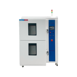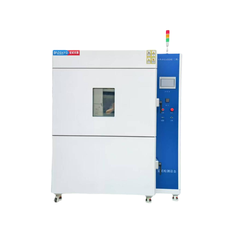
- Technical Parameters
| Item No. | Parameter Name | Technical parameters |
| 1.1 | Equipment Name | Thermal Shock Test Chamber (Three-Chamber Type) |
| 1.2 | Equipment Introduction | Thermal Shock Test Chambers of this series are one of the commonly used equipment in various environmental tests. They are applicable to electronic instruments and meters, materials, electrical engineering, vehicles, metals, aerospace products, electronic products and other components. Specifically, they are used to inspect the performance and various indicators of these components under the environment of rapid alternating high and low temperature or static high and low temperature, as well as for quality management purposes. |
| 1.3 | Equipment Model | BS-42IA |
| 1.4 | Effective Volume | 42L |
| 1.5 | Internal Chamber Dimensions | 400*350*300 (W*H*D)(mm) |
| 1.6 | External Dimensions | 1400*1873*1655(W*H*D) (mm) |
| 1.7 | Temperature Range | High-Temperature Zone Temperature Range: RT ~ 170℃
Low-Temperature Zone Temperature Range: RT ~ -60℃ Test Zone Temperature Range: -40℃ ~ 150℃ |
| 1.8 | Thermal Shock Range | High-Temperature:60℃~150℃
Low-Temperature: -10℃~ -45℃ Room Temperature: Indoor temperature |
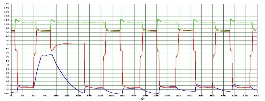
| 1.9 | Thermal Shock and Recovery Time | Thermal Shock Time: 5S
Temperature Recovery Time: 5 min Shock Process (as shown in the figure)
Green represents the heat storage curve of the high-temperature zone Red represents the shock curve of the test zone Blue represents the cold storage curve of the low-temperature zone |
| 1.10 | Temperature Fluctuation | ≤±0.5℃ |
| 1.11 | Temperature Error | ≤±2℃ |
| 1.12 | Temperature Uniformity | ≤±2℃(Temperature Uniformity is defined as the average of the difference between the measured maximum temperature and the measured minimum temperature in each test.) |
| 1.13 | Preheating Zone Temperature Rise Rate | ≥3℃/min (Full-process Non-linear) |
| 1.14 | Precooling Zone Temperature Drop Rate | ≥1℃ (Full-process Non-linear) |
| 1.15 | Functional Requirements | (Air-based) In chamber Space Cooling and Heating
According to the temperature setting, the indoor space reaches the set temperature. It is divided into three parts: high-temperature storage zone, low-temperature storage zone, and test zone. The three zones are independent of each other, and temperature switching is achieved through air dampers. |
| 1.16 | Weight | 550KG |
| 1.17 | Power | 380V/18KW |
| 1.18 | Others | Note & Prohibition for the Test Equipment
1. Note The above performance indicators are values measured under the conditions of: ambient temperature of +25℃, relative humidity ≤ 85% RH, and no test samples loaded. 2. Prohibition This test equipment is prohibited from the following: · The testing or storage of samples of flammable, explosive, or volatile substances. · The testing or storage of samples of corrosive substances. · The testing or storage of biological samples. · The testing or storage of samples with strong electromagnetic emission sources. · The testing or storage of samples of radioactive substances; · The testing or storage of samples that may generate flammable, explosive, volatile, highly toxic, corrosive, or radioactive substances during testing or storage.
|
- Compliant Test Standards
| Item No. | Standards | Explanation of Standards |
| 2.1 | General standards | GJB150.5A-2009 Thermal Shock Test |
| GB/2423.13-2002 Thermal Shock Test | ||
| GJB360B-2009 Thermal Shock Test | ||
| GB2423.1-2008/IEC6008-2-1-2007 Electrical and Electronic Products – Environmental Testing – Part 2: Test Methods – Test A: Low Temperature | ||
| GBT2423.2-2008 Electrical and Electronic Products – Environmental Testing – Part 2: Test Methods – Test B: High Temperature | ||
| GBT 10589-2008 Technical Specifications for Low-Temperature Test Chambers | ||
| GBT 11158-2008 Technical Specifications for High-Temperature Test Chambers | ||
| 2.2 | Acceptance Execution Standards | Manufacturing Standards:GB/T10586-2006,GB/T10592-2008 |
| Verification Standards :GB/T5170.2-2017,GB/T5170.5-2016 | ||
| Technical Standards: Acceptance shall be conducted in accordance with the signed technical index requirements |
- Equipment Structure
| Item No. | Description | Technical Specification Parameters |
| 3.1 | Cabinet Structure | The Precooling Zone, Preheating Zone, and Test Zone are independent of each other. Temperature switching between the three chambers is achieved via air dampers, eliminating the need to move test products.
For ambient temperature shock: Ambient temperature is introduced into the test space by a blower to expel heat or cold from the test space, while the air dampers of the high-temperature tank and low-temperature tank are closed. For low-temperature shock: The air dampers of the high-temperature tank and ambient-temperature tank are closed; the low-temperature tank is connected to the test chamber, instantly transferring prestored cold energy into the test chamber. For high-temperature shock: The air dampers of the low-temperature tank and ambient-temperature tank are closed; the high-temperature tank is connected to the test chamber, instantly transferring prestored heat energy into the test chamber. This design achieves the goal of rapid temperature alternation. |
| 3.2 | Cabinet Material Specifications | Outer Wall Material: 1.2mm cold-rolled steel plate with electrostatic spraying
Inner Wall Material: High-quality heat-resistant and cold-resistant 1.0mm&304 stainless steel plate Cabinet Insulation Material: 100mm glass fiber |
| 3.3 | Insulation Layer | The Preheating Workshop, Precooling Workshop, Ambient-Temperature Shock Chamber, and Test Workshop are thermally insulated with thickened insulation layers. The joints are insulated with high-temperature-resistant epoxy resin boards, which effectively prevent heat cross-transfer to achieve energy-saving goals.
Meanwhile, the inner panels of the cabinet doors for the Preheating Workshop, Precooling Workshop, and Test Workshop are all equipped with epoxy resin boards for thermal insulation. This design effectively prevents heat transfer to the outer surface of the equipment (which would otherwise affect the temperature of the equipment’s installed controls), ensuring safety and reliability. |
| 3.4 | Air Damper | The air dampers are made of SUS304 stainless steel, processed into movable small doors. Each small door is equipped with silicone sealing strips and a thermal insulation layer, and its inner side is insulated with an epoxy resin board—this design effectively prevents heat cross-transfer. The movement of the small doors is driven by air cylinders for switching, featuring automatic cycle control and simple operation. |
| 3.5 | Cabinet Door | The high-temperature zone and low-temperature zone are each equipped with a separate door, both adopting a single-door design. Explosion-proof handles are used, and silicone sealing strips are installed to ensure the cabinet doors are sealed without leakage. |
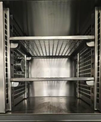
| 3.6 | Test Sample Rack | 2 Pieces of SUS304 Stainless Steel Grid-Type Storage Racks (Load Capacity ≤ 40kg per Piece) |
| 3.7 | Lead Wire Test Hole | Provide test holes with a diameter of 50mm, equipped with corresponding thermal insulation accessories and dedicated sealing soft plugs |
| 3.8 | Air Circulation Duct | The equipment is equipped with built-in high-temperature zones, low-temperature zone air chambers, air circulation ducts, and stainless steel circulation fans. Via the switching of air dampers, heat and cold are uniformly blown out from the inside of the ducts, transferring the temperature stored in the high-temperature tank and low-temperature tank to the test space. This design achieves rapid temperature alternation and uniform distribution of indoor temperature. |
| 3.9 | Power Distribution and Control Cabinet | Main Power Circuit Breaker,Controller,Power Distribution Board,Cooling Fan,Over-Temperature Protector,Air Cylinder,Air Pressure Protector etc. |
| 3.10 | Refrigeration Mechanical Chamber | Internally Installed Refrigeration Units and Accessories |
| 3.11 | Others | LCD Touch-Type Programmable Controller, Basket Initial Position Changeover Switch, Main Power Switch, Running Indicator Light, Abnormal Indicator Light,Completion Indicator Light, Defrosting Indicator Light, Power Indicator Light, USB Communication Interface |
- Circulation System
| Item No. | Description | Technical Specification Parameters |
| 4.1 | Air Outlet Mode | It adopts a forced internal circulation mode, with left-side air outlet and right-side air return switched via air dampers. The air outlet guide vanes can disperse cold and hot air throughout the entire chamber interior, ensuring uniformity and stability. |
 |
||
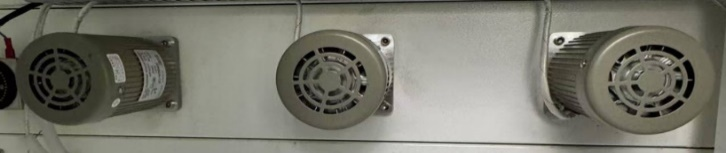
| 4.2 | Circulation Motor | It is a long-shaft motor, installed outside the chamber, avoiding the influence of temperature and humidity inside the chamber. The long shaft extends directly into the interior of the chamber, with silicone insulation and sealing. |
 |
||
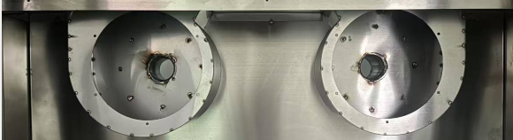
| 4.3 | Centrifugal Impeller | It is a multi-blade centrifugal circulating aluminum wind wheel, featuring light weight, large air volume, and high air pressure. Additionally, it exhibits resistance to high and low temperatures, a small expansion coefficient, and low operating noise. |
 |
||
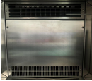
| 4.4 | Circulating Air Duct | The circulating air duct is matched with the refrigeration and heating system, and the sealing plate is closely attached to the evaporator and heating tube, allowing the circulating air to fully absorb the cold energy from the evaporator and the heat energy from the heating tube. |
 |
||
| 4.5 | Sensor | Class A Platinum Resistance PT100+T Temperature and Humidity Sensor, featuring stable operation and accurate detection. |
- Refrigeration System
| Item No. | Description | Technical Specification Parameters |
| 5.1 | Refrigeration Mode | Compressor-Based Refrigeration |
| 5.2 | Compressor | French “Tecumseh” Hermetic Compressor |
| 5.3 | Evaporator | High-Efficiency Multi-Stage Fin-and-Tube Evaporator with Hydrophilic Coating (Thickened Fin Type) |
| 5.4 | Condenser | Shell-and-Tube Condenser (Air-Cooled Type) |
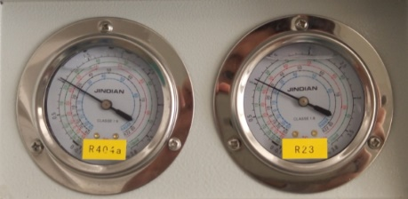
| 5.5 | Refrigerant | Fluoride-Free Eco-Friendly Refrigerant, DuPont (USA) R404A |
| 5.6 | Thermal Expansion Valve | The core control logic of the thermal expansion valve is: The opening degree of the expansion valve is controlled by the superheat degree of the gaseous refrigerant at the evaporator outlet, thereby adjusting the flow rate of refrigerant entering the evaporator. |
| 5.7 | Oil Separator | The core function of the oil separator is to separate the refrigerating oil and refrigerant, allowing each substance to perform its respective function as required and preventing oil films from reducing heat exchange efficiency. |
| 5.8 | Filter-Drier | The filter-drier consists of two parts: the filter and the dryer. The filter is used to block solid particles such as iron filings, welding slag, and dirt, preventing them from clogging the passages; the dryer is used to absorb moisture circulating with the refrigerant, avoiding “ice blockage” inside the pipelines. |
| 5.9 | Solenoid Valve | Danfoss Solenoid Valve (for coarse adjustment of the cooling capacity of the entire refrigeration system) |
| 5.10 | Leak Detection Method | Nitrogen purging and pressure holding for 24 hours is adopted for leak detection testing of all pipelines in the entire system. |
 |
||
| 5.11 | Vibration Damping Design | Compressor Base and Vibration Isolation Treatment: The base features a water-leakage prevention design. It is a self-evaporating waterproof base that effectively prevents condensed water from leaking out. Vibration isolation treatment is applied to moving components such as the compressor and fan, achieving a low-noise design. |
- Heating System
| Item No. | Description | Technical Specification Parameters | |
| 6.1 | Heating Method | It adopts an imported SSR (Solid-State Relay) for driving, featuring contactless control, no noise, no electric arc, and stable reliability. | |
| 6.2 | Heating Tube | It adopts a stainless steel finned nickel-chromium wire high-speed heater. | |
| 6.3 | Heating System and Electrical Components | It is a completely independent system that does not affect the refrigeration and humidification systems. Temperature control is achieved through microcomputer calculation and PID automatic adjustment; the output power changes based on the comparison result between the actual temperature value and the set temperature value, so as to achieve high precision, high efficiency, and high stability. Major low-voltage electrical components all adopt products from well-known brands: “Schneider” AC contactors and thermal overload relays, “OMRON” small intermediate relays, and Delixi signal lamps, switches, and circuit breakers. | 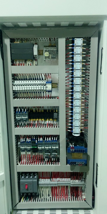 |
- Control System
| Item No. | Description | Technical Specification Parameters |
| 7.1 | Control Method | Color Touch Screen + PLC Control System |
| 7.2 | Screen Display | 7-inch screen with a resolution of 800*480, 65535 true colors, and LED backlight display; direct display of temperature and humidity set values (SV) and actual values (PV); Chinese/English language switchable display with true-color touch input; capable of displaying execution program number, segment number, remaining time, cycle times, and operation time; program editing and graphic curve display. |
| 7.3 | Temperature and Humidity setting | Set it independently according to the test temperature range requirements.
|
| 7.4 | Data Logging | Built-in recording program, the memory in the controller can store 3 months of 24hour operation data. It can automatically generate temperature and humidity curve files, data, operation records, alarm records, etc., and can display set values and actual values, cycle numbers, temperature segments, temperature values, time, etc. in both digital and graphical forms. |
| 7.5 | External Connection | Communication methods such as USB, RS485, and LAN ports are supported, enabling external connection to a computer for full-function control, data storage, printing, and recording. |
| 7.6 | Running Mode | Rated value/program/slope running mode. |
| 7.7 | Input Method | RT100×2 (dry bulb and wet bulb) / 4~20mA, both built-in simultaneously |
| 7.8 | Output Method | Temperature×1, Humidity×1, END×1, RUN×1, T1~T4, TROUBLE×1, H1×1, TIME SIGNAL×3. |
| 7.9 | Display Precision | Temperature:0.01℃
Humidity:0.01%RHT Time:0.01 seconds |
| 7.10 | System Capacity | 1~120 test programs (i.e., can be divided into 120 program groups), maximum 1~1200 steps (i.e., 1200 action steps), and single-step time up to 9999 hours 59 minutes. |
| 7.11 | Login Method | Chinese/English Name Login, Chinese/English Test Login, Operation Time Display. |
| 7.12 | Deviation Correction | It prevents parameter deviations caused by various factors; after correction, the temperature and humidity values can be more accurate and standardized. |
| 7.13 | System Functions | Sequence Control, Reservation Control, Power-off Recovery, Fault Display. |
| 7.14 | Password Control | Multi-level password protection can be set to prevent unauthorized use by non-operators and unauthorized modification of internal parameters. |